We often find that customers use general-purpose operational amplifiers such as LM321 for current sensing applications. This is one of the traditional operational amplifiers that have been in use for decades. These traditional operational amplifiers are low cost and are used in countless applications. However, sometimes some engineers report that these op amps are malfunctioning in their current detection circuits. When we looked at the op amp units, they worked as expected. So where is the problem?
Because the op amp is “universal” does not mean “can be used for all purposes.” Current sensing applications require precision. Current sensing is commonly used in power management and overcurrent protection applications. Imagine an imprecise world. When your phone’s battery is almost exhausted, the battery indicator may be 8%. You may design an overcurrent circuit that is triggered at 100A, but find that the protection circuit does not activate until 150A, and all downstream components are damaged. This is the difference between universal and precise.
The key to a precision operational amplifier is the input offset voltage. The common mode rejection ratio (CMRR) and power supply rejection ratio (PSRR) also have better specifications, but both of these parameters can be regarded as the input offset voltage that varies with the common mode voltage or the power supply voltage. What is the input offset voltage? The input offset voltage is the inherent bias of the input of each operational amplifier and is due to the slight mismatch of the input transistors caused by the manufacturing process. In school, we learned that the ideal op amp has zero input offset voltage, but we know that this is not the case in the real world.
Traditional general-purpose operational amplifiers such as LM321 have VOS =±7mV (maximum value), and modern general-purpose operational amplifiers such as NCS20071 have VOS =±3.5 mV (maximum value). This maximum specification is distributed around zero. This means that most of the time randomly selected devices will exhibit near-zero bias. You can be sure that your prototype circuit works perfectly with the commonly used LM321, but when the circuit enters mass production, you may find that the proportion of failures is quite large. This is because the manufacturing process produces part-to-part variation, and some devices are close to the limit. You should always design the maximum input offset voltage for the circuit.
We sometimes see customers forget to check the limits of the circuit in the worst case: input offset voltage limit, CMRR limit, resistor network tolerance, temperature effect, etc.
Compared with the LM321 and NCS20071 general-purpose operational amplifiers, the new NCS21911 precision operational amplifier has a maximum offset VOS = ±25μV (microvolts) due to its chopper-stabilized structure. How much difference does the offset voltage actually make? Let us consider such a situation: the shunt voltage drop is a fixed 50mV, as shown in Figure 1.
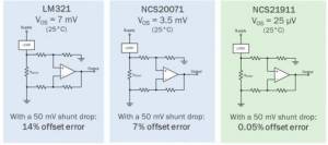
Figure 1. Comparison of input offset voltage and the resulting output offset error
Amplifiers with input offset voltages of 7 mV and 3.5 mV have significant output offset errors.
We can take a closer look at the example of Vos=7 mv in Figure 2.
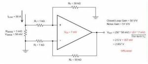
Figure 2. Output error caused by low-side current detection and input offset voltage
By choosing a precision op amp such as NCS21911, the error caused by the input offset voltage is almost negligible in this circuit example. It not only improves the output accuracy, there is even some margin to reduce the size of the detection resistor, and still maintain the required accuracy.
Since the low offset voltage supports the reduction of the sense resistor value while maintaining the same accuracy, as shown in Figure 3, the efficiency is greatly improved. What happens when the size of the sense resistor is reduced? The sense resistor consumes less power, which means that lower watt and lower-cost resistors can be used, and the smaller physical size sense resistor ultimately occupies less space on the PCB, which improves the overall energy efficiency of the system and reduces losses.
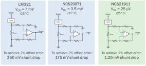
Figure 3. Comparison of input offset voltage and the resulting shunt voltage drop under fixed accuracy requirements.
The smaller the shunt voltage drop, the higher the efficiency.
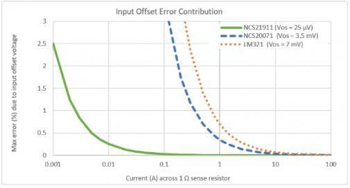
In many applications, the load current flowing through the sense resistor is variable. Sometimes when customers try to measure current around 0A, they find that the error increases significantly; this is normal and should be expected. When the current drops to zero, the error percentage becomes infinite. This current detection circuit is used to measure current; it is not used for accurate measurement when there is no current.
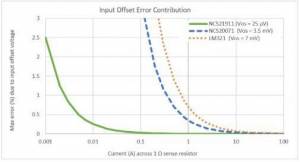
Figure 4. The accuracy increases as the current increases
Note the change in error due to the input offset voltage. Even when the detection voltage drops, the 25μV offset of NCS21911 supports relatively accurate measurement.
It seems that small improvements in efficiency and precision can save bills of materials, printed circuit board (PCB) costs, and electricity bills. Although choosing a cheaper op amp may save some money in the early stage, considering that the final system-level savings may be your advantage, using a reasonably priced precision op amp is more feasible.
In many applications, general-purpose operational amplifiers will work normally. Even the traditional LM321 can also work in current detection applications where the corresponding circuit has been designed. Remember, you should expect relatively high output errors. Alternatively, the size of the sense resistor should be large to obtain a voltage drop that is sufficiently larger than the input offset voltage.
For low-side current detection, turning to precision op amps improves accuracy and system energy efficiency. The NCS21911 precision operational amplifier has a standard output pin, which allows it to replace general operational amplifiers such as LM321 and NCS20071 with a simple plug-in.
