The digital valve adopts an NTC thermistor as a temperature sensor, forms a simple voltage divider circuit with a fixed resistor as a water temperature measurement circuit, and uses the built-in 8-bit A/D converter of the PIC16C71 microcontroller to convert the analog voltage on the thermistor into digital voltage. The PIC16C71 microcontroller controls the DC motor to drive the water mixing valve to adjust the mixing ratio of cold and hot water, achieving water temperature adjustment. The control circuit diagram is given, and the parameter selection and temperature measurement accuracy of the water temperature measurement circuit is discussed in detail. Experiments and analysis show that choosing an NTC thermistor and voltage divider with a larger resistance value can better solve the problem of thermal breakdown caused by the larger power consumption of the thermistor.
With the development of society, various water heaters and hot water pipes have entered thousands of households. People have various requirements for the water temperature on different occasions. It is often necessary to mix hot and cold water to the required temperature.
As a valuable technology, the intelligent digital valve can control the water temperature of various water heaters and pipeline hot water and can quickly and accurately adjust the required temperature of hot water. It is able to be used in showers, washes, and other places requiring hot water with a constant temperature. This design is in line with this need, with the PIC16C71 microcontroller as the core, this digital valve is able to control the mechanical part to automatically adjust the mixing ratio of cold water and hot water, to realize the automatic control of the water temperature, and to solve the problems of water temperature fluctuating cold and hot caused by fluctuations in water pressure and changes in water temperature or changes in water output. This way has a more obvious saving effect than manual adjustment of water temperature.
1. System structure and working principle
Hot water and tap water are used as the two inputs of the control valve, and the mixing valve is used to control the input amount and proportion of cold and hot water, and the mixed water flows out through the water outlet for use by users. The temperature sensor installed at the water outlet senses the temperature at the water outlet and transmits it to the microcontroller through the temperature measurement circuit. The composition of the digital valve is shown in the figure below. When the water outlet switch is turned on, the microcontroller compares the temperature at the water outlet measured by the temperature sensor with the set temperature. When necessary, the microcontroller PIC16C71 controls the DC motor to drive the water mixing valve to adjust the ratio of cold and hot water entering the water valve. Thereby, the temperature of the outlet water is controlled. When the motor turns to the end, the single-chip microcomputer gets the corresponding signal to stop the motor from continuing to rotate in the same direction.
Set the water temperature within the range of 25 to 50°C through the temperature rise or temperature drop button, and the LED digital tube displays the set water temperature value. If the set temperature does not match the temperature detected by the sensor, according to the temperature difference between the two, the single-chip microcomputer outputs pulse voltage signals of different widths to control the DC motor to rotate at different speeds and drives the cold and hot water mixing valve through the transmission mechanism to change the inflow ratio of cold and hot water. When the external conditions change again, such as the water pressure decreases or increases, there is a temperature difference between the water temperature of the outlet pipe and the set temperature. At this time, the single-chip microcomputer controls the rotation of the motor again and automatically adjusts the water temperature, so that the water temperature of the water outlet is automatically adjusted to make the water temperature of the water outlet automatically consistent with the set water temperature.
System block diagram
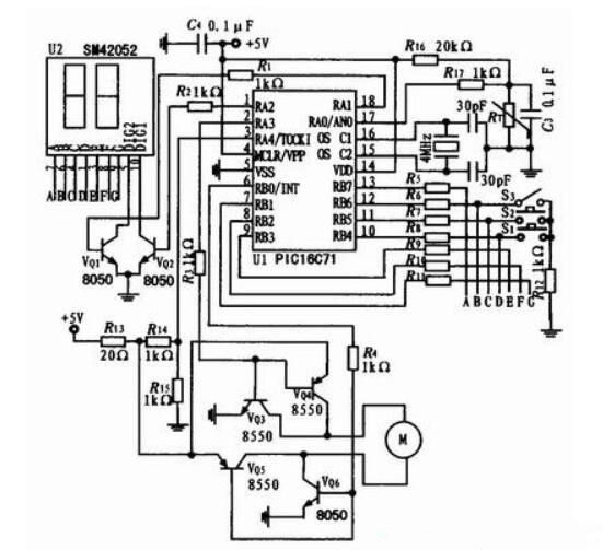
Digital valve circuit
2. Control panel and circuit
The design of the control panel button should be minimized, and it is easy to use, reasonable in function, easy to control and operate, and the instrument can display the set temperature. The control panel is shown in the figure below. The 2-digit LED digital tube on the left side of the panel is used to display the preset water temperature. The temperature rise button and temperature drop button on the upper right of the panel are used to increase and decrease the temperature of the preset water temperature respectively. The lower right of the panel is a manual switch, which determines the switch of the water valve and the size of the water outlet. When it is set to “off”, it is in the non-working state.
A circuit diagram of a control valve is shown above. The system uses a low-voltage DC power supply, uses PIC16C71 single-chip microcomputer for control, and realizes various functions through program control.
2.1 Keyboard input and output display circuit
When designing the input circuit, the characteristics of the software-controlled weak pull-up circuit of the PORTB port in PIC16C71 are fully used. The keyboard inquiry circuit is composed of resistors R6, R7, R8, buttons S1, S2, S3, and resistor R12, and the status of the buttons is inquired through pins RB6, RB5, and RB4. When the RB4~RB6 pins are used as input terminals, they are connected to the buttons S1, S2, and S3 respectively. S1 is the temperature increase setting button, S2 is the temperature drop setting button, and S3 is the handle switch associated key. RB6, switch S3, and R12 form a water state query input circuit and the water state is input by the RB6 pin. The set water temperature is output by RB1~RB8 through the current limiting resistors R5~R11 and then output by the two-digit LED digital tube. The output of RA1 and RA2 controls VQ1 and VQ2 as the position control of the LED digital tube.
2.2 DC motor drive circuit
The turn-on and turn-off of the transistors VQ3-VQ6 are controlled by the output levels of pins RA3 and RB0, which are used to control the polarity reversal of the power supply of the DC motor M. The voltage drop value of the sampled DC motor M is sent to another input channel of the A/D converter of the PIC16C71 chip. The voltage drop across the motor is sampled by R14, R15 and then input to the A/D converter by the RA4 pin. It is then read by the program for judging the motor position and control.
3. A/D data processing
During the test, it is found that if the temperature data after A/D conversion of PIC16C71 is directly used for temperature control without processing, the motor will malfunction from time to time. Even if various filter circuits are added to the temperature measurement circuit, there is still no improvement. Therefore, it is inferred that the interference may come from the inside of the A/D conversion module. Considering the slow change of field temperature in this system, the sliding window averaging method is suitable for digital filtering. After the digital filtering method is used to average the 16 consecutive temperature data obtained after A/D conversion, the noise after A/D conversion is effectively eliminated.
4. Conclusion
The digital valve for controlling water temperature is powered by a low-voltage DC power supply to ensure safety. The water outlet switch and the flow rate are controlled by a single handle. The water temperature is preset by the button and displayed by the digital tube. The operation is simple. The outlet water temperature can be set between 25 and 50°C, and the resolution is 1°C. If the water temperature of the water outlet is inconsistent with the set water temperature, the LED digital tube will flash to remind you to pay attention. At the same time, the single-chip microcomputer generates pulses to control the speed and forward and reverse rotation of the motor according to the height and difference between the two and drives the mixer water valve through the transmission mechanism to adjust the water inlet ratio of cold and hot water. The water valve is used in conjunction with a domestic water heater, and can automatically and quickly adjust the required water temperature, which can prevent the stimulation of hot and cold water, make bathing comfortable, and features an obvious water-saving effect.