Introduction
Controller Area Network (CAN) is a serial data communication protocol developed by BOSCH in 1986 to solve the data communication between the measurement and execution components inside the car. Its network model structure includes a physical layer, data link layer, and application layer, with twisted pair as the signal transmission medium, the communication rate can reach up to 1Mbps (40m), and the direct transmission distance can reach up to 10km/5Kbit/s. Up to 110 devices can be connected to the bus, which is especially suitable for networks with high real-time requirements. It features a multi-master working mode, excellent stability and real-time performance, mature arbitration and synchronization technology, an open bus structure, high-speed communication of short messages, long-distance communication capabilities, super error correction and expansion functions, simple control, and low application cost. CAN has been increasingly applied to the field of network control systems and has been recognized as one of the most promising field bus technologies.
USB (Universal Serial Bus) is a protocol specification launched by seven companies led by Intel in 1995 to unify various peripheral interfaces of the computer. The interface of four wires (two power wires and two data lines) is used to realize the communication between any device and PC. It has the characteristics of plug and play, extensive software and hardware support, low power consumption, low price, high data transmission rate, good scalability, flexible use, high standardization of hardware structure, and complete bus topology. It has a strong vitality and is widely used in the control system with the computer as the host computer.
With the rapid development of computer technology, PC, the controller that has adopted USB as a universal bus and universal interface standard, has almost become the first choice for controlling terminals in various fields. Through the USB interface, after installing the necessary application software and drivers, the PC can be connected to each control system. Therefore, in order to improve the high efficiency of the application and the convenience of control, and the combination of the generality of USB with the professionalism of CAN to achieve complementary advantages, it is necessary to design a high-speed USB2.0-CAN adapter card to realize USB2.0. 0 The conversion between the communication protocol and the CAN bus communication protocol.
System Structure
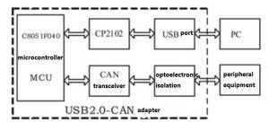
The system mainly includes three parts: microcontroller, USB interface, and control part of CAN interface (see Figure 1). Among them, C8051F040 is used as the system microcontroller. The USB interface function controller adopts CP2102 USB to UART bridge chip. Among them, C8051F040 is responsible for exchanging data with the CAN network as a CAN bus controller, CP2102 realizes the conversion between USB port information format and serial port format, and finally, C8051F040 operates the serial port to exchange data with CP2102 to realize the conversion from USB2.0 to CAN bus protocol.
Hardware Implementation
CP2102
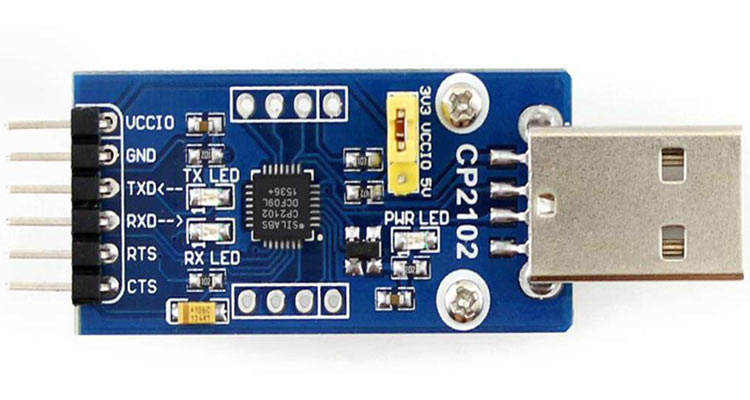
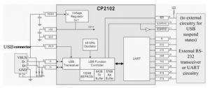
CP2102 is a USB to UART bridge chip from Silicon Labs. It has the characteristics of high integration, high speed, low price, and simple development. It can easily realize the conversion from USB to UART with the simplest external circuit and the fewest external devices. CP2102 contains USB2.0 full-speed function controller, USB transceiver, oscillator, and asynchronous serial data bus (UART) with all modem control signals. The internal structure of CP2102 is shown in Figure 2. There is a built-in protocol for communication with the computer. When working, the free and practical COM port device driver provided allows a product based on CP2102 to be used as a port, which is commonly referred to as generating a virtual port, the circuit can work without any external USB device, and the working characteristics can meet the transmission baud rate requirements of the CAN bus.
Microcontroller
The system uses the mixed-signal system-level microcontroller C8051F040 introduced by Silicon Laboratories as the system controller. The integrated CAN controller includes a CAN core, message RAM (independent of the CIP-51 core), message processing unit, control registers, etc., but there is no driver of the physical layer. To realize the interface with the CAN bus, an interface controller is needed, such as 82C250, TJA1050, and so on. The data receiving and filtering are all done by the CAN controller, without the participation of the CIP-51 core. In this way, the system resources occupied during CAN communication are minimized. The CIP-51 core configures the CAN controller and realizes data interaction through its internal special function registers.
Circuit Design
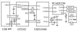
The system circuit is shown in Figure 3, which consists of CP2102, C8051F040, CAN driver chip PCA82C250, and optoelectronic isolation chip 6N137. The RTX and TXD pins of CP2102 are the receiving and output terminals of the serial port respectively and are connected to the corresponding pins of the microcontroller. USB’s termination and resume signaling support facilitate power management of the CP2102 device as well as external circuits. When a termination signal is detected on the bus, the CP2102 will enter termination mode. When entering the termination mode, CP2102 will send SUSPEND and signal. However, SUSPEND is temporarily high during the CP2102 reset. To avoid this, a 10kΩ resistor is required to ensure that it remains low during reset. PCA82C250 is a CAN transceiver, which can increase the bus driving capability. The Rs terminal is connected to the ground, and the system is in a high-speed working mode. 6N137 is an optoelectronic isolation chip. After the CAN bus signals CANTX and CANRX come out from C8051F040, they are electrically isolated by high-speed optocoupler 6N137 respectively, and then driven by CAN bus controller interface chip 82C250, and then connected to the CAN data line. 6N137 realizes the electrical isolation between the intelligent node and the CAN bus, which not only improves the reliability of the node and the anti-interference ability of the system but also protects the bus and other nodes on the bus. The 124Ω resistor pair at both ends of the bus prevents reflections when the communication signal is transmitted to the end of the wire.
The Realization of Protocol Conversion Between USB and CAN
The design realizes the protocol conversion and forwarding between USB data and CAN data on the basis of fully complying with USB and CAN protocols. In the design process, there are contradictions between the high speed of USB and the low speed of CAN, the large data packets of USB and the small data packets of CAN, which must be solved carefully, otherwise, it may cause data loss, unreliable protocol conversion, and unstable equipment work. In this design, both USB and CAN adopt the receiving interrupt mode, and the data packets of USB and CAN are stored first, and then further processed as a buffer. When the data is received by the interrupt service process, the receiving buffer is released only when the data is accurately collected, and new data is refused to be received before that. When data is sent, it is necessary to confirm that the send buffer is available before writing data. Since the interface chips at both ends have internal send and receive buffers, the main task of the main program is to complete data forwarding and provide a handshake protocol for communication synchronization to prevent data loss and sequence errors.
Compared with the CAN bus transmission rate, the USB bus rate is much higher, and the 128-byte buffer is also much larger than the 8-byte buffer of the CAN bus chip. Therefore, sending data to the CAN interface requires unpacking and repacking, which is a relatively slow operation and is sent by the timed query. The CAN receive a task, directly forwarding the 8-byte data received by the CAN interface to the USB interface sending buffer each time, and uses two semaphores (CAN-rcv, USB-wr) to complete the data synchronization operation. A total of 4 tasks are coordinated and completed in the data forwarding work:
(1) USB interrupt subsequent processing tasks
When CP2102 receives data or completes sending, it will trigger the interrupt program to run. The interrupt handler needs to simply notify the task that an interrupt has occurred to minimize the time the interrupt is closed. Therefore, this task has the highest priority, and once it starts running, it will not wait for other events, and it will be processed as soon as possible. This task notifies other tasks to perform subsequent data processing or forwarding according to different interruption reasons of the USB interface.
(2) Control endpoint information processing tasks
This task is notified when the USB interface receives the USB protocol information from the host. According to the requirements of the host, it responds to the host according to the data format of the USB protocol specification. Mainly used for information exchange with the host during USB device enumeration. At other times, this task does not consume processor time.
(3) CAN bus transmission task
When the USB interface has new data to be forwarded to the CAN bus, the USB interrupt subsequent processing task informs this task to run. Read the data in the receiving buffer of the USB chip into the memory buffer, then decompose it into data packets of less than or equal to 8 bytes, add the CAN bus protocol data packet header, and send it into the sending buffer of the C8051F040. The main processing time of the microprocessor is the disassembly and repackaging of USB data packets. This task consumes the processor the most time. Each time the CAN send task waits for the USB receive interrupt to trigger the USB_rd semaphore, it starts to read the CP2102 receive buffer data to the memory array Ep2out_Buf and then uses the query sending method to send the data to the send buffer of the C8051F040 with 8 bytes each time. During the query process, if the C8051F040 is in the process of sending, sleep the task for 3 clock ticks <5ms), and then query again to avoid occupying the processor for a long time.
(4) CAN bus receiving task
After the CAN bus receives data, since the data packet has only 8 bytes at most, it can be put into the USB interface chip sending buffer at one time and read by the host computer. This task consumes very little processor time. The main purpose is to coordinate the synchronization of data forwarding between the CAN bus and the USB bus so that the data packets are received in the original order, and the previous data packet that has not been sent is not overwritten to avoid data loss. CAN receive interrupt first read C8051F040 interrupt register and clear the interrupt flag. The CAN-rcv semaphore is then triggered to enable the CAN to receive a task to run. The CAN receives a task and then waits for the USB to complete the transmission of the interrupt to trigger the USB-wr semaphore, indicating that the USB interface can send new data. Because the USB interface buffer is large and the sending speed is fast, the CAN receiving task directly sends the data received by the CAN into the sending buffer of the USB interface chip CP2012, then the CAN is opened to receive interrupt.
Conclusion
The design is based on fully complying with the USB and CAN protocols. Both USB and CAN adopt the receiving interrupt method. Through the handshake protocol of communication synchronization, the protocol conversion and forwarding between USB data and CAN data are realized, which is a good solution to the contradiction between the high speed of the USB and the low speed of the CAN, the large data packet of the USB and the small data packet of the CAN, and ensures the integrity of the data and the reliable conversion of the protocol, making the professional operation and practice of CAN more flexible and convenient through USB.
Also click: latest injector apk for free fire 2022