In recent years, with the continuous development of new technologies, batteries as a power source not only play an important role in transportation (railway, subway, ship), power generation, communication, aerospace, chemical industry, traditional automobile and other industries, but also have begun to be used as a power source or power auxiliary power in electric vehicle (EV) and hybrid electric vehicle (HEV) field. Compared with the one-time rechargeable battery, the two notable features of the battery are multiple recycling as well as high efficiency and energy saving. When the car is not started, it must rely on the battery to supply power to the starter until the engine is driven to rotate. When the battery voltage is insufficient or the battery is damaged, it is difficult to provide enough power and the engine cannot run. Therefore, this paper proposes the design of a low battery warning system for automobile batteries based on LM741. When the battery voltage drops to a certain limit, the circuit determines whether the battery is working normally by installing an acousto-optic signal warning system, and reminds the user to take corresponding measures (ie, recharge or replace the battery).
1. LM741 Working Principle
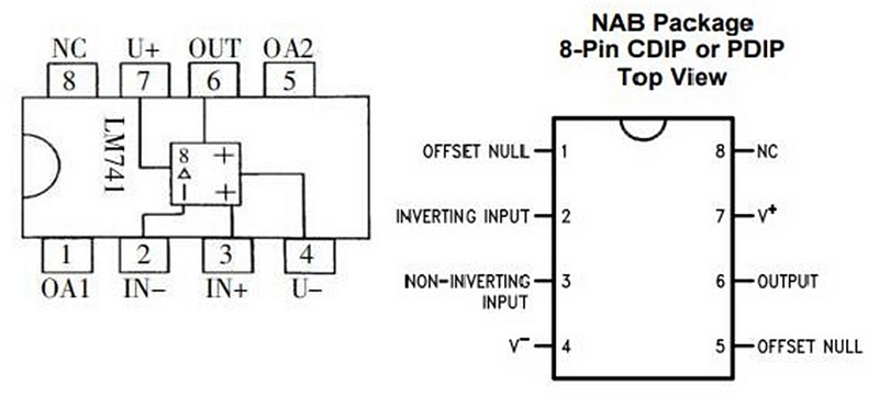
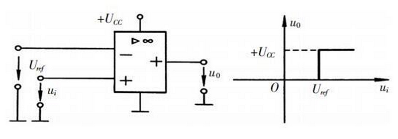
LM741 is a dual power integrated operational amplifier, which is usually used in automotive amplifier circuits, or used as voltage comparators in automotive circuits. Figure 1 is the pin diagram of LM741 and the function of each pin. In this system, the LM741 works in the nonlinear region and constitutes a voltage comparator. Its function is to compare the two signals (analog input signal and reference signal) sent to the input of the integrated op-amp and obtain the result in the form of high and low levels at the output. Between its two input voltages, one is the reference voltage, and the other is the input voltage to be compared. When the two voltages are not equal, the output voltage of the integrated op-amp is either equal to the positive power supply voltage or equal to zero, that is, only output two voltage values at the output end, positive supply voltage or zero. Figure 2 is a voltage comparator with a non-inverting input and its voltage transfer curve. The non-inverting input terminal and the inverting input terminal of the integrated operational amplifier respectively introduce the input signal ui and the reference voltage signal Uref. When LM741 is used as a voltage comparator, compare the input voltage and the reference voltage. When ui>Uref, the integrated operational amplifier outputs a high level, that is, uo=UCC; when ui<Uref, the integrated operational amplifier outputs a low level, that is, uo=0.
2. Overall Design of the System
The low battery alarm system for automotive batteries is mainly composed of four parts: the reference power circuit, the sampling circuit, the voltage comparator circuit, and the output circuit. The reference power supply circuit is composed of a voltage regulator tube and a current limiting resistor, which are added to the inverting input of the voltage comparator and provide a reference voltage for it; the sampling circuit is composed of two resistors in series to form a series voltage divider function, which is used as the input signal of the whole circuit, and is used to take a part of the battery voltage and compare it with the reference voltage; the voltage comparator circuit judges the output high level or low level by comparing the voltage of the reference power supply circuit and the voltage of the sampling circuit; the output circuit determines whether the light-emitting diode is in a conducting state according to the received output voltage of the voltage comparator, thereby sending out an alarm signal, indicating that the battery power is too low. The structure of the alarm system is shown in Figure 3.