How Do Fiber Optic Cables Work?
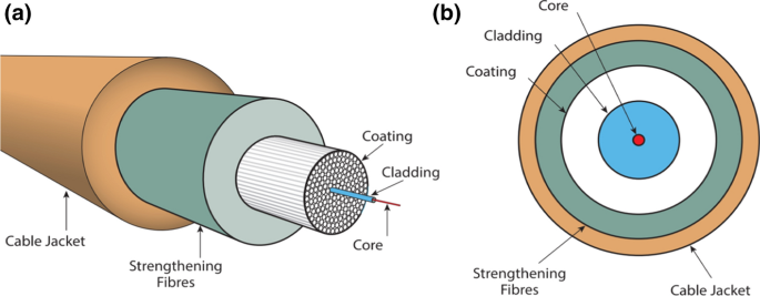
A fiber optic cable is made of glass strands. Each strand is slightly thicker than a human hair. Each strand has a core in the middle that allows light to pass through. Each core is surrounded by a second layer of glass called cladding, which bounces light inward to prevent signal loss while also allowing light to pass through the cable’s bends. Total internal reflection describes how light in a fiber-optic cable travels through the core (hallway) by constantly bouncing off the cladding (mirror-lined walls).
Coatings are the multiple layers of plastic that surround the fiber. These coatings act as a buffer, absorbing shock and adding an extra layer of protection.
Single Mode vs Multimode Fiber Cables
In a network, multimode and single mode fiber has different transmission styles. Because of its larger core, some light beams may travel directly, while others may bounce off the cladding. Single mode fiber cables have a diametric core that is up to 5 times smaller than multimode cables. It only allows one mode of light to pass through the core.
Multimode fiber comes in two core lengths: 50m and 62.5m. Because of its relatively wide core, it can carry multiple data streams at 850nm or 1300nm wavelengths at the same time. Due to high dispersion and attenuation rates, multimode fiber is typically used to carry a high volume of data over relatively short distances. It uses a light-emitting diode (LED) or Vertical Cavity Surface Emitting Laser (VCSEL) as its light source.
Single mode fiber has much less internal reflection as light passes through it, which reduces attenuation and enables much faster data transfer over long distances. Multimode fiber cabling, on the other hand, dramatically increases the amount of reflection, resulting in higher dispersion and attenuation rates and, as a result, increased bandwidth delivery over shorter distances
Colors
The colors of these two types of fiber cables make it easy to distinguish them when selecting cables. The majority of single-mode cables are yellow, while multimode cables are usually orange or aqua.
Diameter
The core of all-fiber cables transports light to transmit data. The primary distinction between single mode vs multimode fiber cables is the size of their cores. Single-mode fiber optic cables have a much smaller core diameter than multimode optical fiber cables. The 9-micron standard used in broadcasting and production reduces attenuation and allows signals to travel further. The multimode core diameters in A/V are 50 or 62.5 microns, allowing more data to pass through the fibers at the same time.
Transmission Distance
Single-mode fibers are better suited for long-distance applications due to their high bandwidth capability. Since multimode fibers have a larger core size, the modal dispersion, or the overlapping of pulses, increases over larger distances; thus positioning this type of fiber to be the best choice for shorter-distance applications.
Tight-buffered Breakout/Distribution Cable
Breakout Cable
Breakout Cable Structure
The breakout cable is also referred to as a fan-out cable. As shown in the diagram, a breakout cable is made up of two or more simplex cables bundled around a central strength member. Each fiber has its jacket, and they are all packaged together inside the same outer jacket. As a result, when running through building walls, breakout cables can be separated into individual simplex cables for separate use. Breakout cables are typically designed with a tight buffer and fiber counts ranging from 2 to 24 fibers.
Breakout Cable System Layout
For direct connectivity, a tight-buffered breakout cable is the best option. Because each fiber has its aramid strength member for connector tie-off, the sub cables can be directly connected to equipment in most situations without fear of fiber damage or connector/fiber end-face damage. Look at the image below:
Distribution Cable
Distribution Cable Structure
Distribution cable, as opposed to breakout cable, is smaller and lighter in weight. For up to 144 fibers, distribution cable fiber counts can be higher than breakout cable fiber counts. Many fibers may not be used right away but can be saved for future use. Although the distribution cable has a more compact design, the tight-buffered fibers inside the cable are only protected by a single outer jacket, as shown in the image below. Nonetheless, this has made the distribution fiber optic cable easier to handle and strip for field termination.
Distribution Cable System Layout
Tight-buffered distribution cables are simple to route and their 900m tight-buffered fiber allows for fast and reliable field terminations. The terminated fibers are placed in a patch panel, as shown in the image below, and jumper cables are used to connect the patch panel and equipment.
Why Use Fiber Cables instead of Copper Cables?
Fast data transmission, thinner, lighter cables, and extended signal range are just a few of the advantages that make fiber optic cable an excellent choice for corporate data networking and telecommunications.
EMI (Electromagnetic Interference)
Copper wires generate an electromagnetic field that can cause signaling errors in other cables. Fiber cables, on the other hand, do not generate electromagnetic interference (EMI). They are also unaffected by EMI. You can put them right next to industrial equipment and not worry about it.
High-Speed Data Transmission
Fiber optic cables use light pulses and are made of tiny strands of glass about the size of human hair. The speed of photons versus the speed of electrons can be compared in fiber optic versus copper transmission. Photons travel at the speed of light, whereas electrons in copper travel at less than 1% the speed of light. Copper currently has a top speed of 40 Gbps, whereas OM5 fiber has a top speed of 100 Gbps. What’s more, unlike cable broadband and DSL, fiber optic connections do not degrade over distance, allowing for consistent premium data transfer speeds.
High Bandwidth Level
The primary advantage of optical fiber communication over electrical cable transmission is its high bandwidth capability (nearly 10Gps) over long distances due to extremely low loss at the same specific wavelengths (e.g. 1.3 um and 1.55 um).
Fiber also reduces latency, allowing for faster download and upload times as well as faster access to resources. Because of its low loss, fiber can also transport data over longer distances without causing delays or interruptions.
More Secure
A broken or damaged optical fiber can be detected very quickly by using a variety of monitoring techniques, such as monitoring actual power transmission or pilot signal transmission. Without such efficient monitoring techniques, copper cable carrying a current can completely short out or even cause a fire if it is damaged, old, or worn.
Light Weight, Water-Proof, and Extended Lifespan
Fiber cables are rough one-quarter the diameter and one-tenth the weight of copper cables, making them easier to install and promoting better airflow in rack enclosures. Furthermore, unlike copper cables, fiber optic cable is not affected by temperature changes, bad weather, or moisture. The actual lifespan of a fiber optic cable should be at least ten years, but they frequently last much longer.
Fiber Optic Connector Types
SC (Subscriber Connector)
SC is a push-pull device that delivers highly accurate alignment in a fiber-optic link by utilizing a ceramic ferrule. SC connectors are equipped with a dependable snap-in locking mechanism that latches with a simple push-pull motion. They are a low-cost, long-lasting option that can withstand 1,000 mating cycles. This connector can be used in both simplex and duplex mode. The new SC connectors simplify installation, even more, maximize yield, and provide guaranteed insertion and return loss performance comparable to factory-terminated connectors.
LC (Lucent Connector/Little Connector)
The LC, which is also a push-pull connector, uses a latch rather than the SC locking tab and has a smaller ferrule, making it a small form factor connector. With half the footprint of the SC connector, it is extremely popular in datacoms and other high-density patch applications, as its small size and latches feature make it ideal for densely populated racks/panels.
FC (Ferrule Connector/Fixed Connector)
For durability, an FC connector is made of an all-zirconia ceramic ferrule. For repeatability and interpretability, they have a high-performance thread mounting system and a keyed body. They are mostly used with single mode fibers in telephone, instrument, and high-speed communication links. The design is similar to that of an ST connector, but it has a threaded connection that makes it more suitable for high vibration environments.
ST (Straight Tip)
AT&T developed the ST connectors shortly after the FC arrived. They are commonly used in fiber optic networking applications. They can be used for both short-distance and long-distance applications. Stick and twist is an older technology, but it is still widely used on data networks and has a large install base.
Fiber Optic Cables Applications
There are numerous applications for fiber optic cables. Telecommunication companies use them to transmit telephone signals, Internet communication signals, and cable television signals.
Ethernet
Optic fibers are used to connect servers and users in several network setups, as well as to improve data transfer accuracy and speed. Fiber optic cables, as opposed to traditional copper wiring, are lighter, less bulky, more flexible, and can carry large amounts of data at very high speeds. As a result, fiber optic cables are increasingly being used for internet cables.
Auto Industry
Following Mercedes-successful Benz’s introduction of plastic optical fiber (POF) in automobile networking systems in 1998, the Media Oriented Systems Transport (MOST) standard—a stable and robust network protocol for optimum multimedia of entertainment and information—was developed.
Fiber optic cables are used to illuminate both the exterior and interior of automobiles. They play an important role in lighting and safety measures. Fiber optic cables can transmit signals between different parts of a vehicle at high speeds.
Television
Fibre delivery technologies provide numerous advantages to both TV companies and their customers. Because they have more bandwidth and faster speeds, they are ideal for signal transmission for HD televisions. In addition, fiber optic cables are less expensive than copper wires.
Medical
Endoscopy relies heavily on optical communication (non-intrusive surgical methods). In such a procedure, a small, bright light is used to illuminate the surgery area inside the body, allowing it to reduce the number and size of incisions. Biomedical research and microscopy also make use of fiber optics.
Cloud Data Storage
With the growing popularity of cloud computing, there is a greater demand for data capacity and higher bandwidth. The performance and productivity of cloud computing solutions are dependent on your internet connection because they are internet-based servers. Many businesses are switching to fiber-optic connectivity to make the most of the cloud. Cloud computing would be ineffective if there was insufficient bandwidth.
How to Clean Fiber Optic Cable?
It is critical to clean fiber optics before installation. A clean cable is not guaranteed by a new cable, and the installation process can introduce dust and other contaminants. Before inserting a fiber optic cable into a connector, always clean the end of the cable.
There are two types of fiber optic connector applications that require cleaning: free connectors on a fiber optic patch cable or fiber pig-tail and connectors plugged into patch panels or other hardware devices and equipment.
To clean fiber optic cables, you can use one of several methods. Here’s one cleaning method you can try:
To dislodge any larger, loose particles, blow the surface of the fiber with CDA.
In the center of lens tissue, place a few drops of an appropriate cleaning solution, such as spectroscopic-grade isopropyl alcohol or methanol.
Grip the fiber gently by the cable or connector. Place the wet tissue section on the optical surface and slowly move it across the fiber.
Examine the fiber surface with a magnifier, video inspection tool, or optical loop in bright light. If any contaminants or streaks are visible, repeat the process with new lens tissue.
When you’re finished cleaning, put a protective cover on the end of the cable or reinsert the fiber to prevent recontamination.
To avoid damage while cleaning, use extreme caution throughout the process and follow the guidelines below:
While blowing, do not tip the CDA can, as this may result in the release of liquid, which will contaminate the fiber surface.
Dry lens paper is extremely abrasive and should never be used.
Acetone should never be used to clean fiber optic surfaces.
Inserting the lens tissue into the methanol or isopropyl alcohol can contaminate the liquid. Drip the cleaning solution onto the tissue instead.