
Under normal circumstances, we can know the current of the resistor by amplifying the voltage and reading it with ADC. But if the voltage on the detection resistor is very different from the voltage of the system, the detection becomes more difficult. Therefore, today we introduce a different solution-wireless.
The analog current detection IC is a compact solution. The voltage difference it can withstand is limited by the semiconductor process. It is difficult for us to find a device with a rated voltage exceeding 100V. If the common-mode voltage of the sense resistor changes rapidly or swings up and down the system ground voltage, these circuits cannot accurately measure.
The volume of digital isolation technology is a bit large. It can work with high precision and can usually withstand several thousand volts. These circuits need to isolate the power supply, but sometimes it can be integrated in an isolator. If the sense resistor is physically separated from the main system, long wires or cables may also be used.
The wireless current detection circuit overcomes these limitations. It allows the entire circuit to float along with the common-mode voltage of the detection resistor, and wirelessly transmits measurement data in the air. The voltage limit is gone. The detection resistor can be located anywhere, without the need to lay out cables. If the circuit power consumption is very low, then we do not need to isolate the power supply. A small battery can keep it running for many years.
Design Scheme
The current detection circuit in Figure 1 is based on the chopper-stabilized operational amplifier LTC2063. It is used to amplify the voltage drop across the sense resistor. The AD7988 micropower SAR ADC digitizes the value and reports the result through an SPI interface. LTP5901-IPM is a radio module. It contains not only the radio, but also the networking firmware required to automatically form an IP mesh network.
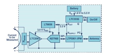
Figure 1
The low-power wireless current detection circuit consists of a low-power chopper operational amplifier (used to amplify the detection voltage). It uses a low-power ADC and a reference voltage source for digital processing, and is connected to the SmartMesh IP radio module. The battery is output to a low-power DC-DC converter to obtain a constant power supply, and the charge obtained from the battery is recorded at the same time. LTP5901-IPM has a built-in microprocessor to read the AD7988 ADC SPI port. The LTC3335 is a low-power DC-DC power supply that converts the battery voltage to a constant output voltage.
Signal Chain
LTC2063 is an ultra-low power chopper stabilized operational amplifier with a maximum supply current of 2μA, which is particularly suitable for battery-powered applications. The offset voltage is less than 10 μV, so it can measure very small voltage drops without loss of accuracy.
Figure 2 shows the LTC2063 configuration used to amplify the voltage on the 10 mΩ sense resistor and perform level shifting. We choose an appropriate gain to map the ±10 mV full-scale input of the sense resistor to the full-scale range close to the output. It is centered at 1.5 V. This amplified signal is input to a 16-bit SAR ADC. AD7988 has extremely low standby current and good DC accuracy. When the sampling rate is low, the ADC automatically shuts down between conversions. The average power consumption at 1 kSPS is as low as 10 μA.
LT6656 is used for bias amplifier, level shift resistor and ADC reference input. The LT6656 reference voltage source consumes less than 1 μA and can drive loads up to 5 mA. Its pressure difference is very low. Therefore, even with a 3.3 V system power supply. It is also easy to output a precise 3 V voltage.
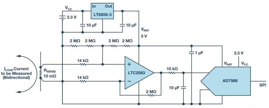
Figure 2
The current detection circuit in the figure floats with the detection resistor voltage. The chopper operational amplifier LTC2063 amplifies the detection voltage and biases it to the middle rail of the AD7988 ADC. The LT6656-3 provides a precision 3 V reference voltage source.
Power Management
The LTC3335 is a nanoampere power buck-boost converter with integrated coulomb counter. It is configured to generate a regulated 3.3 V output from an input power supply of 1.8 V to 5.5 V. This allows the circuit to be powered by the power of two alkaline primary batteries. For duty-cycle wireless applications, the load current can easily vary from 1 μA to 20 mA. It depends on whether the radio is in working mode or sleep mode. The static power consumption of the LTC3335 at no load is only 680 nA. Therefore, when the radio and signal chain are in sleep mode, the operating power consumption of the entire circuit is very low.
Wireless Networking
LTP5901-IPM is a complete radio module, including radio transceiver, embedded microprocessor and SmartMesh IP networking software. LTP5901-IPM performs two functions in this application: wireless networking and management. When multiple SmartMesh IP terminals are powered on near the network manager, these terminals will automatically recognize each other and form a wireless mesh network. The entire network automatically synchronizes time. This means that each radio only powers up within a very short specific time interval. Therefore, each node is not only a source of sensor information, but also acts as a routing node to pass data from other nodes to the manager. In this way, a high-reliability, low-power grid network is formed. There are multiple paths from each node to the manager. However, the working power consumption of all nodes is very low.
Total Power Consumption
The total power consumption of the complete application circuit depends on many factors, including how often the signal chain takes a reading, how the nodes are configured in the network, and so on. For a terminal that reports once per second, the typical power consumption of the measurement circuit is less than 5 μA. The typical power consumption of the radio may be 40 μA. A small battery can keep it working for several years.
Conclusion
The combination of Linear Technology and ADI signal chain, power management, and wireless networking products allows us to design true wireless current detection circuits. From(easybom)