LC Definition
An LC circuit, also known as a resonant circuit, tank circuit, or tuned circuit, is a circuit that contains an inductor (denoted by the letter L) and a capacitor (denoted by the letter C) connected. The circuit can be used as an electrical resonator, and the energy stored oscillates when the circuit resonates.
LC circuits are used both to generate signals of specific frequencies and to separate signals of specific frequencies from more complex signals. They are key components in many electronic devices, such as oscillators, filters, tuners, and mixer circuits.
The inductive circuit is an idealized model because it assumes that there is no energy dissipated by resistance. A practical implementation of any LC circuit will contain losses due to the small but non-zero resistance of components and connecting wires. The purpose of an LC circuit is usually to oscillate with minimal damping, so the resistance value of the resistor should be as small as possible. Although there are no lossless circuits in practice, studying such ideal circuits is beneficial for both understanding and physical intuition. For circuit models with resistors, see RLC circuits.
The most basic passive linear elements are resistors (R), capacitors (C), and inductive elements (L). These components can be used to form 4 different electrical circuits: RC circuit, RL circuit, LC circuit, and RLC circuit, these names are derived from the abbreviations of the components used in each. They embody some properties that are important to analog electronics. The LC circuit functions as passive filters.
RLC circuit is a circuit structure composed of electronic components: resistor R, inductor L, and capacitor C. There are two general structures of RLC circuits: series type and parallel type. It can be used for simple harmonic oscillation, bandpass filters, or bandstop filters.
RC circuit, an abbreviation of Resistor-Capacitance circuit, an RC circuit consists of a resistor and a capacitor. According to their arrangement, it can be divided into RC series circuit and RC parallel circuit; pure RC parallel circuit cannot resonate, because the resistor does not store energy, LC parallel circuit can resonate. RC circuits are widely used in analog circuits and pulse digital circuits. If an RC parallel circuit is connected in series in the circuit, it will attenuate low-frequency signals, and if it is connected in parallel, it will attenuate high-frequency signals, that is, filtering.
Learn more about the RC circuit.
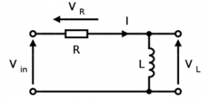
RL circuit, an abbreviation of resistor-inductor circuit, is also known as RL filter or RL network. It is the simplest infinite pulse response filter. It is composed of a resistor and an inductive element connected in series or parallel and is driven by a voltage source.
Resonant Frequency
In the circuit containing capacitors and inductors, if the capacitors and inductors are connected in parallel, the situation may appear in a small period: the voltage of the capacitor gradually increases, while the current gradually decreases; the current of the inductor gradually decreases. As the voltage increases, the voltage across the inductor gradually decreases. And in another small-time period: the voltage of the capacitor gradually decreases, and the current gradually increases; the current of the inductor gradually decreases, and the voltage of the inductor gradually increases. The increase of the voltage can reach a positive maximum value, and the decrease of the voltage can also reach a negative maximum value. Similarly, the direction of the current will also change in the positive and negative directions during this process, which is called the electrical oscillation of the circuit. When the sinusoidal frequency of the external input voltage of the circuit reaches a certain frequency (that is, the resonant frequency of the circuit), the inductive reactance of the resonant circuit is equal to the capacitive reactance, Z=R, and the resonant circuit is purely resistive to the outside, that is, resonance. When resonance occurs, the resonant circuit amplifies the input by a factor of Q, where Q is the quality factor.
For a resonant circuit composed of an inductor L and a capacitor C, the circuit impedance Z is equal to R+i(ωL-1/ωC), where R is the resistance, ωL is the inductive reactance of the inductor, and 1/ωC is the capacitive reactance of the capacitor. Assuming that the quality factor Q is 28, then for the resonant circuit of the inductor L and the capacitor C in parallel, the current is increased by 28 times. For a resonant circuit with inductor L and capacitor C in series, the voltage is increased by a factor of 28. Radio equipment often uses resonant circuits for tuning, filtering, etc.
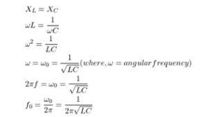
The resonant frequency of the circuit is also called the natural frequency of the circuit. Since the inductive reactance of the circuit at resonance is equal to the capacitive reactance, that is, ωL=1/ωC, the resonant angular frequency ω0=1/√LC. Since ω0=2Πf0, the resonant frequency f0=1/2Π√LC, which is only determined by the inherent parameters L and C of the circuit itself. Q≈1/R √(L/C)
Types of LC circuits
LC circuits can be divided into parallel LC circuits and series LC circuits according to the connection of inductors and capacitors.
1. series LC circuit
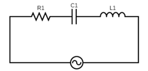
Let’s first look at the series LC circuit. The inductor and capacitor are connected in series, as shown in the figure below.
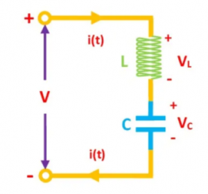
The sum of the voltages across the capacitor and inductor is the sum of the total voltages across the open terminals V = VL + VC. The current in the LC circuit and the Ve terminal is equal to the current through the inductor (L) and capacitor (C) I = IL = IC.
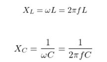
The inductive reactance of the inductor is proportional to the frequency, and the capacitive reactance of the capacitor is inversely proportional to the frequency. Therefore, when the frequency f increases, the inductive reactance XL of the inductor increases, but the capacitive reactance XC of the capacitor decreases.
When the frequency f reaches a certain value, the inductive and capacitive reactances of the LC series circuit are equal, and series LC circuit resonance occurs.
Then we go back to the impedance Z of the series LC circuit.
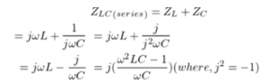
When the circuit works at the resonant frequency f0, according to the formula of f0 above, Z=0 can be obtained. That is to say, in the series LC circuit, the inductive reactance and the capacitive reactance cancel each other out, presenting short-circuit characteristics to the outside, and the current in the circuit is the largest. Therefore, a series LC circuit when connected in series with the load will act as a bandpass filter with zero impedance at the resonant frequency.
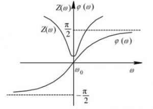
When the frequency is lower than the resonance frequency f0, XC is much larger than XL, and the circuit is capacitive; when the operating frequency is higher than the resonance frequency f0, XL is much larger than XC, and the circuit is inductive. When the working frequency is equal to the resonant frequency f0, the current is the largest, and only the resistor works in the circuit.
2. Parallel LC circuit
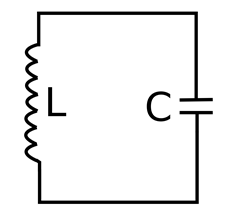
Let’s look at another form of LC circuit – a parallel LC circuit. In this circuit, both the inductor and capacitor are connected in parallel as shown.
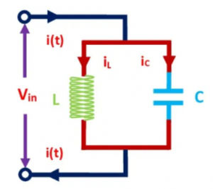
The voltage across the inductor and capacitor of the parallel resonant circuit is the same V = VL = VC. The total current flowing through a parallel LC circuit is equal to the sum of the current through the inductor and the capacitor I = IL + IC. Under resonance conditions, when the inductive reactance (XL) is equal to the capacitive reactance (XC), the reactive branch currents are equal and opposite. Therefore, they cancel each other out to minimize the current in the circuit, and in this state, the total impedance is maximized. The resonant frequency of the parallel LC circuit is as follows:
![]()
Let’s look again at the circuit impedance Z at resonance.
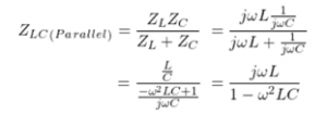
Bringing the resonant frequency f0 into the above impedance formula, we can be obtained that the impedance is infinite, and the circuit is in an open state. Therefore, when the parallel LC circuit is connected in series with the load, it will act as a band-stop filter with infinite impedance at the resonant frequency. A parallel LC circuit in parallel with the load will act as a bandpass filter.
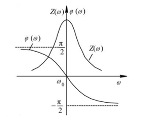
When the frequency is lower than the resonant frequency f0, XL is much larger than XC, and the circuit is inductive; when the operating frequency is higher than the resonant frequency f0, XC is much larger than XL, and the circuit is capacitive. When the operating frequency is equal to the resonant frequency f0, the current is the smallest and the impedance is the largest.
LC Circuits Applications
In the following part, Easybom will give a brief introduction to the applications of LC circuits in the following electronics projects.
The application of the LC circuit in electronic technology is very extensive. Because of its selectivity to frequency, it is often used as a load of high-frequency and intermediate-frequency amplifiers in transmitting and receiving equipment; the LC circuit is an important part of the oscillator. It is used as an absorption circuit in the electronic circuit to filter out interference signals, etc., here are some examples.
- Signal selection

radio input loop circuit
The input loop circuit of an AM radio is shown in the figure below. In the circuit, L1 is the receiving antenna of the radio input loop, L2 and C are the LC circuit to form the radio frequency selection circuit, and L3 sends the selected radio signal to the radio receiving circuit.
The radio antenna receives electromagnetic waves from different radio stations in the air and adjusts C to make L2 and C resonate on the carrier frequency of the desired radio station. At this time, the maximum current flows through L2, and the radio signal is selected. Adjust C to make L2 and C resonate on the carrier frequencies of different radio stations so that programs from different radio stations can be received.
- Signal filtering
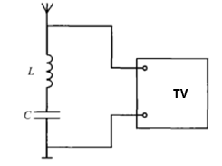
IF suppression circuit in the TV
The TV will output a 38MHz IF signal after mixing by the high-frequency tuner. If there is a 38MHz signal in the external signal entering the TV, it will cause serious interference to the TV’s IF signal, so the external 38MHz signal must be filtered as shown in the figure, the series LC circuit is connected in parallel with the input end of the TV, and the LC circuit resonates at 38MHz. According to the characteristics of series resonance, it presents a small resistance to the 38MHz signal, which is equivalent to short-circuiting the 38MHz signal to the ground, preventing external intermediate frequency signals such as other TV sets from entering the TV and interfering with the work of the local intermediate frequency amplifier, as well as prevents the IF signal of the machine from radiating out through the antenna to interfere with the work of other machines. Since the LC loop presents a high impedance to the TV signal, it will not affect the normal operation of the TV.
- Component measurement
Q table schematic
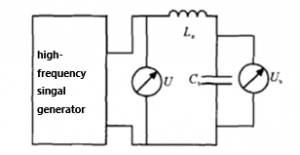
The Q meter is an instrument used to measure parameters such as quality factor, inductance, capacitance, etc. It works by using the characteristics of the resonant circuit, and its principle can be illustrated in the figure below.
The signal source uses a high-frequency signal generator with variable frequency and output voltage. During measurement, change the frequency while keeping the output voltage of the power supply constant.
Measure the Q value of the inductor coil Lx, connect Lx in series with a standard capacitor Cb and then connect it to the output of the high-frequency signal generator, adjust the capacitance of Cb or the frequency of the high-frequency signal generator to make the circuit reach resonance, at this time the voltage across Cb reaches a maximum value and is equal to Q times the supply voltage. Both ends of the standard capacitor Cb can be connected to a voltmeter or a Q meter in parallel, and the Q value should be read out. Generally, the output frequency of the Q meter and the capacitance value of the standard capacitor Cb are marked on a scale.
Using the series LC circuit, the inductance of the coil Lx under test can be obtained based on the known resonance frequency f0 and the standard capacitance Cb.