General Description
The AXICOM IM series 2 form C slim-sized signal relays come in different performance types and variable terminals structures for specific instrumentation requirements (take reference from the product code definition table below). The IM series supports 4G telecom/signal/switching transition with switching power of 60W/62.5VA. Besides, its rated coil power is relatively low, which indicates more current should be taken to switch successfully. What’s more, it has a high shock resistance mechanism, making it rather reliable in the harsh operating environments.

Features
- IP67 sealing class cabinet-free automation for excellent durability
- Capable for high surge and dielectric application situations
- RoHS compliant , Pb-free
- Condensed size benefits in low-space consumption
- High contact stability version available
- Support both bifurcated & single contacts
IM03GR CAD Model
Symbol

Footprints

3D Model

Composition and Package Dimension (SMT Gull Wings version, in mm)

IM03GR Important Specifications
- Additional Feature – RELEASE TIME WITH DIODE IN PARALLEL
- Contact Resistance – 50mOhm
- Insulation Resistance – 1000000000Ohm
- Contact Voltage(DC)-Max – 220V
- Contact Form – DPDT (2 Form C)
- Coil Voltage – 5VDC
- Switching Voltage – 250VAC 220VDC -Max
- Contact Rating (Current) – 2A
- Must Release Voltage – 0.5VDC
- Operating Frequency-Min – 100MHz
- Operating Frequency-Max – 900MHz
- Contact/Output Supply Type – AC/DC
- Relay Action – MOMENTARY
- Coil Operate Voltage(DC) – 3.5V
- Isolation Max – 18.8 dB
Instructions
Where to Use IM03GR
This signal relay family has a wide range of application aspects including Telecommunication, access and transmission equipment, optical network terminals, modems, Thermostat controls, fire and security equipment, consumer electronics, industrial control, medical equipment, HVAC and more.
How to Use IM03GR

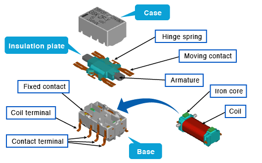
The above are the main components of surface mount signal relays. The coil is secondary molded, resulting in excellent insulation between the coil and the contact while remaining compact.

This simplified circuit diagram shows how IM03GR is used as a high-efficiency switch that control open/closed status of the circuit. It can operate with a maximum 220V DC voltage and 250V AC voltage supply.
User Guidelines

The diagram illustrates the switching resistive load changing “cliff” (which generally indicates the contact ratings). The shadowed area depicted recommended application range of the device. Make sure to select the correct type of relay for the electrical load you’re managing, as well as one that matches your durability requirements.

Although the relay will operate if the applied voltage is greater than the operational voltage, it is necessary to provide only the rated voltage to the coil to account for variations in coil resistance, etc., caused by variances in power supply type, voltage fluctuations, and temperature increases. Also, exercise caution because if the voltage used exceeds the maximum that may be applied, issues such as layer shorts and coil burnout may occur. Precautions for coil input are listed in the section below. In order to avoid issues, please refer to it.
(Summarized by Easybom)
About the Manufacturer
Many sectors are served by TE Connectivity P&B, previously Tyco Electronics P&B, including appliance, HVAC, industrial control, computer peripheral, and security. P&B has a wide range of relays and circuit breakers to satisfy your needs. For PC board and panel/plug-in mounting, electromechanical, solid state, and time delay relays are available.
IM03GR Alternatives
IM03DGR, G6K-2F-RF-T-TR03 DC5, IM03CGR, G6K-2F-RF-DC5, G6K-2F-RF-T DC5, G6K-2F-RF-S-DC5
Datasheets
Unfortunately the IM03GR datasheet is not available on Easybom, you can check out the manufacturer’s official website.
Conclusion
Due to its gold-pasted contact and bifurcated crossbar construction, the IM series signal relays provide exceptional contact reliability even with a tiny signal load.