General Description
AD590 is a current output type two-terminal temperature sensor using the relationship between the forward current of the PN junction and the temperature, and its output current is proportional to the absolute temperature. The low cost of a single-chip integrated circuit and the absence of supporting circuitry make it an attractive alternative for many temperature measurement applications. The AD590 is suitable for any temperature sensing application below 150°C using conventional electrical temperature sensors. When applying the AD590, linearization circuits, precision voltage amplifiers, resistance measurement circuits, and cold junction compensation are not required.
AD590 has the advantages of excellent linearity, stable performance, high sensitivity, no compensation, small heat capacity, strong anti-interference ability, long-distance temperature measurement, and convenient use. The device acts as a high impedance, constant current regulator with a regulation factor of 1 µA/K over the 4V to 30V supply voltage range. The on-chip film resistors are laser trimmed and can be used to calibrate the device to output 298.2 µA at 298.2K (25°C).
AD590 can be widely used in various refrigerators, air conditioners, granaries, freezers, industrial instruments, and various temperature measurement and control fields.
AD590 Pinout Configuration
AD590 pin diagram

AD590 Circuit Diagram
AD590 circuit diagram
How to Use AD590
The AD590 working principle has been illustrated as follows.
When the measured temperature is constant, AD590 is a constant current source, connect it with the DC power supply of 5~30V, and connect a resistor with a constant value of 1 KΩ in series at the output end, the current flowing through this resistor is proportional to the measured temperature. At this time, there is a voltage signal of 1mV/K at the endpoints of the resistor. The basic circuit is shown in the figure below.

The core circuit of the temperature sensing part
The figure is the temperature control part circuit of the integrated PN junction that utilizes the sensor UBE characteristic. Among them, T1 and T2 play the role of constant current and can be used for the triggering sense of the collector currents I1 and I2 of the left and right branches; T3 and T4 are temperature-sensing transistors. The materials and processes of the two tubes are exactly the same, but T3 is essentially made up of n transistors in parallel, so its junction area is n times that of T4. The emitter junction voltages UBE3 and UBE4 of T3 and T4 are added to the resistor R after being connected in series with reversed polarity, so the voltage on the upper end of R is ΔUBE. Therefore, the current I1 is:
I1=ΔUBE/R=(KT/q)(lnn)/R
For AD590, n=8, in this way, the total current of the circuit will be proportional to the thermodynamic temperature T, and the output voltage proportional to T can be obtained by leading this current to the load resistance RL. The constant current characteristic is utilized, so the output is not affected by the signal voltage and the wire resistance. The resistor R in the figure is a film resistor formed on a silicon board, and its resistance value has been corrected by a laser so that an I value of 1 μA/K can be obtained at the reference temperature.
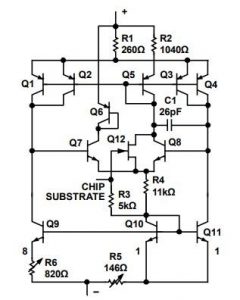
The figure below shows the internal circuit of AD590, T1 ~ T4 in the figure are equivalent to T1, 2, T9, T11 are equivalent to T3, T4 in the figure below. R5 and R6 are low-temperature coefficient resistors made of thin-film technology for adjustment before leaving the factory. T7, T8, and T10 are symmetrical Wilson circuits used to increase impedance. T5, T12, and T10 are the start-up circuits, where T5 is the constant bias diode.
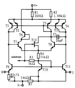
AD590 Internal Circuit
T6 can be used to prevent damage to the circuit when the power supply is reversely connected, and can also make the left and right branches symmetrical. R1, R2 are emitter feedback resistors, which can be used to further increase the impedance. T1 to T4 are connections designed for thermal effects. While C1 and R4 can be used to prevent parasitic oscillations. The design of this circuit makes the emitter currents of T9, T10, and T11 equal and equal to 1/3 of the total current I of the entire circuit. The emitter junction area ratio of T9 and T11 is 8:1, and the emitter junction areas of T10 and T11 are equal.
The emitter junction voltages of T9 and T11 are connected in series with opposite polarities and then applied to resistors R5 and R6, so it can be written as:
ΔUBE=(R6-2 R5) I/3
There is only the emitter current of T9 on R6, and in addition to the emitter current from T10, there is also the emitter current from T11 on R5, so the voltage drop on R5 is 2/3 of that of R5.
According to the above formula, it is not difficult to see that if you want to change ΔUBE, you can adjust R6 after adjusting R5. The effect of increasing R5 is the same as reducing R6, and the result will reduce ΔUBE. However, changing R5 has a more pronounced effect on ΔUBE because the coefficient in front of it is larger. In fact, the laser is used to correct R5 for coarse adjustment and R6 for fine adjustment, and finally make the total current I reach 1 μA/K under 250°C.
AD590 Application
In the figure below, the AD590 sensor is used as a thermometer circuit that is able to measure temperature from -55℃ to +150℃ with an output voltage of 1 mV/°K in a remote temperature sensing application. This is the first example of the AD590 sensor application that Easybom will elaborate on in detail. In order to read out in degrees Celsius, its output must be offset by 273.2 mA as the fact that it measures absolute temperature.
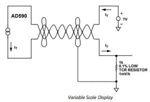
Series connection of AD590 units is able to show the minimum temperature value among all the sensed temperatures. And parallel connection can indicate the average value of the sensed temperature. The circuit below shows the way to realize differential temperature measurements.

As shown in the figure below, R1 and R2 are used to trim the output of the operational amplifier so as to yield the desired temperature difference. If there is a radical difference between V+ and V-, the internal dissipation will be different, resulting in a differential internal temperature rise. Depending on this effect, the ambient thermal resistance can be measured in fluid-level detectors, anemometry, and other applications.

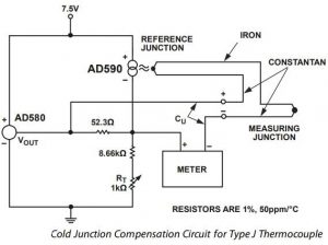
In the figure below, the AD590 is used to detect the reference junction temperature in a cold junction compensation circuit for a Type J thermocouple. This is the first example of the AD590 application that Easybom will elaborate on in detail. In this circuit, the thermocouple reference for ambient temperatures between 15℃ and 35℃ with compensation accuracy of ±0.5°C substitute for an ice-bath. Adjust RT for a proper meter reading while the measuring junction is kept at a known reference temperature, which works as the way to calibrate the circuit. Pay attention to the voltage reference and the resistors, both of which are the primary contributor to error.
AD590 Datasheet Download
If you are interested in the electronic component AD590 or you run into some problems in your related project, look through the AD590 datasheet provided by Easybom to have a deep insight into it.
Conclusion
Because the AD590 temperature sensor has high precision, low price, no auxiliary power supply, and good linearity. Based on the fact that the device’s output power is proportional to absolute temperature, applications for temperature measurement include correction of cold junction compensation and dispersion compensation, as well as flow velocity measurement, standard fluidity, or anemometric measurements. The AD590 can also be used in subtle sensing applications. This device is sensitive to voltage drops on long lines due to its high impedance output circuit. According to its output characteristics, the application of AD590 is also diversified: the current can be converted into a CMOS multiplex or the supply voltage can also be converted into a logic gate output.