Outline: Power Supply Noise and Bypass Capacitor
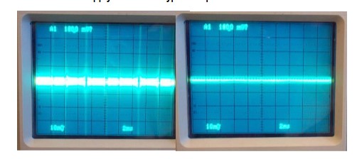
It’s well known that DC (direct current) is applied in almost all digital circuits such as TVs, amplifiers, LED, computers, microcontrollers, and so on. Every time an effectual load is pulled up in a circuit, the process of dividing current and regular spikes would inevitably produce a noise that can cause the voltage to vacillate. Excessive AC ripples in a circuit can lead to inaccurate DC measurement or worse even abate the circuit.
In consideration of cost and package size, putting as many resistors as possible is unrealistic for industrial practice. Therefore, engineers often take measures like filtering, post-regulation, and bypassing to decrease noise from the power supply. Today let’s talk about one of the most pervasive and cost-effective ways to eliminate power supply noise – bypassing.
To sum up, a bypass capacitor is applied to reduce power supply noise by providing a lower resistance at high frequencies to the circuit (and a relatively high resistance at lower frequencies – DC signal), which means a certain amount of AC signals bypass the ground through the bypass capacitor rather than hinder the DC signa
Using a Bypass Capacitor
- Applications
Except for bypassing noises in analog and digital circuits as mentioned, bypass capacitors can be put in use for several other applications with different means.
- Compensations of Current Demands
Bypass Capacitors can be utilized to offer compensations for necessary current demands for a loudspeaker whose signals are casually affected by the amplifier.
- Charge Reservoirs
In digital circuits with microcontrollers or microprocessors, bypass capacitors play a role as the charge reservoirs.
- Offer Instantaneous Current
In circumstances where a rather high frequency is put on the switch to control logic gates, bypass capacitors can function to offer a large current in the switching process.
- Placement Guidelines
The image above is a typical assignment of bypass capacitors on a breadboard from
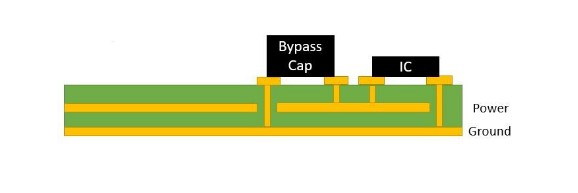
the lateral view. Principles of placement can be concluded as follows.
- The most ideal assignment, a bypass cap should be assigned just on the power/ground and underneath the load/IC for the reason that long trace length increases the inductance and the circuit’s overall impedance, which influences the resonant frequency of the capacitor and obstacles noise-suppress efficiency.
- It is suggested to use multiple bypass caps in parallel especially in a circuit where many components are set, which results in larger ripples, to accomplish a wide bandwidth. Remember to arrange the smallest value capacitor closest to the power supply and others ascending to it by value. We’ll discuss it in the later sections.
Difference between a Bypass Capacitor and a Decoupling Capacitor
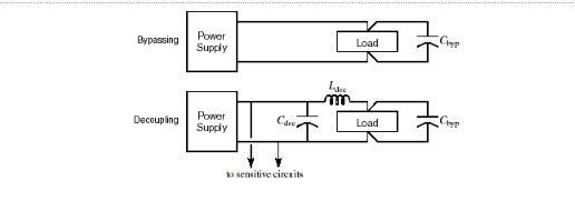
As a matter of fact, bypass capacitors and decoupling capacitors have little difference essentially and they are terms used interchangeably in many applications. However, they are still distinct from each other to some degree.
- For the same circuit, the bypass capacitor takes the high-frequency noise in the input signal as the filtering object and the high-frequency, while the decoupling capacitor takes the interference of the output signal as the filtering object.
- Bypass capacitors are utilized to bypass the noise while decoupling capacitors are implemented to buff the noise.
- For bypassing function, usually just one bypass capacitor is needed in the circuit. But, it is common sense to use two capacitors within which the one that has a lower µF is put near the load/IC.
How to Choose a Right Bypass Capacitor
- Size
Generally, the smaller the bypass capacitor you need to meet the higher the frequency of the circuits. For most hobbyists’ DIY PCB works, a 0.1 µF can manage the noise. More specifically, the value of a bypass capacitor is supposed to be at least 1/10th or less of the emitter resistor to ensure the ability to shunt AC noise to the ground. That’s why we advised such an arrangement that put bypass caps in ascending order of value from the power pin Given this information, a formula might help calculate out the size that best suits you.
f=frac12tR (tR = rise time)
Besides, the capacity to provide instantaneous current is one prominent specification that can be calculated using this equation.
C=fracI*N* ∆t ∆V
Here ∆t stands for time that capacitor needs to charge the line; ∆V is equal to the tolerated drop in VCC; “I” denotes the minimum amount of current to switch one output from a low to high; “N” means switching a number of the outputs.
- Type
Monolithic ceramic capacitors beat other capacitors as the most common-use bypass capacitors thanks to their short-price, constant active time, wide value range, and variable package forms.
If you got a larger budget, pricey choices include OSCON, Tantalum capacitors, and Aluminum Electrolytic capacitors.
Among these three types, OSCON is the top high-end capacitor type providing low parasitic, full operating temperature range as well as a wide frequency range. If you are searching bypass caps for low-voltage applications, the Tantalum capacitor would work to your satisfaction. Aluminum Electrolytic capacitors are polarized products especially excellent in handling ripple current coupled capacity for low-to-medium frequencies.